|
|
 |
|
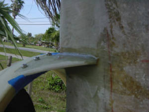
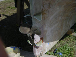
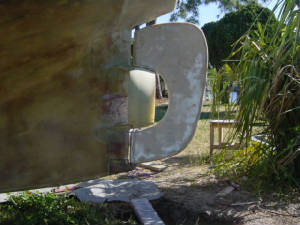
Installation has finally begun, grinding away parts of the winglets to fit the hull and making sure alignment with the
main shaft is critical.
|
|
|
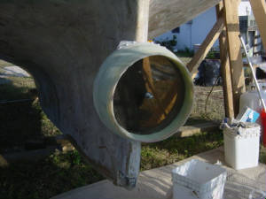
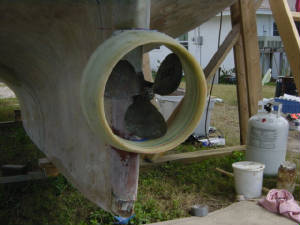
A plastic disc was made to align the shaft hole with the inside of the ring where the clearance between the
prop and the nozzle are most critical. A line inside the nozzle marks the closest point of propeller to nozzle clearance.
The disc fits the cutlass bearing hole and gives the best fit and alignment. The winglet supports are ground away until
the nozzle fits in place, time consuming but critical to function. Next step is to glass the winglets to the hull, at
this point the nozzle can be removed and re-installed at any time with assurance that it will fit back in that same position
everytime.
Enter images and other content here
|
|
|
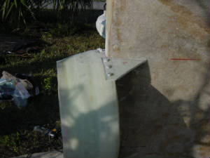
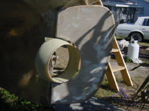
Using the alignment plate to simulate the Propeller the nozzle is in place having already been fitted to
the hull. Using a the same expoxy resin mixed with milled fibers a slurry was made to attach the winglet supports.
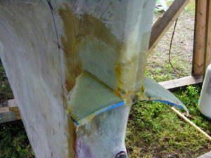
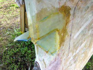
When the resin has curred the nozzle is removed to allow 17 oz. Bi-axe cloth to be layed around the supports, top and bottom.
We're putting about 6 layers on each winglet, that should make things as strong. We could be overbuilding this thing
but there will be forces on the thrust ring that we can't measure and want to make sure it's strong.
Enter images and other content here
|
|
|
Enter images and other content here
|
|
|
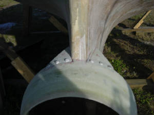
With the nozzle completed, the winglet mounts installed and glassed in place, the new rudder opening cut,
it's time to see if everything fits.....
"It fits", no more explaination needed"....
Enter images and other content here
|
|
|
Enter supporting content here
.
|
|
|
|